Battery Cycler
The Battery Cycler block can be used to simulate cycles of:
- Constant Current (CC) discharge
- Rest
- Constant Current/Constant Voltage (CCCV) charge
- Rest
Steps 1 through 4 are considered a single cycle by the block.
This block emulates a typical experiment often performed in battery labs. Simulating this behaviour with Breathe Simulate can, for example:
- Provide insight into the internal states the battery would have during these empirical tests,
- Screen for suitable rest times to avoid encroaching the initial temperature at the start of each cycle, but maximising capacity throughput,
- Predict the length of a cycle for capacity and validation programme planning,
- Investigate model accuracy based on known data.

Specifying the cycling conditions
Defining the conditions of a cycle
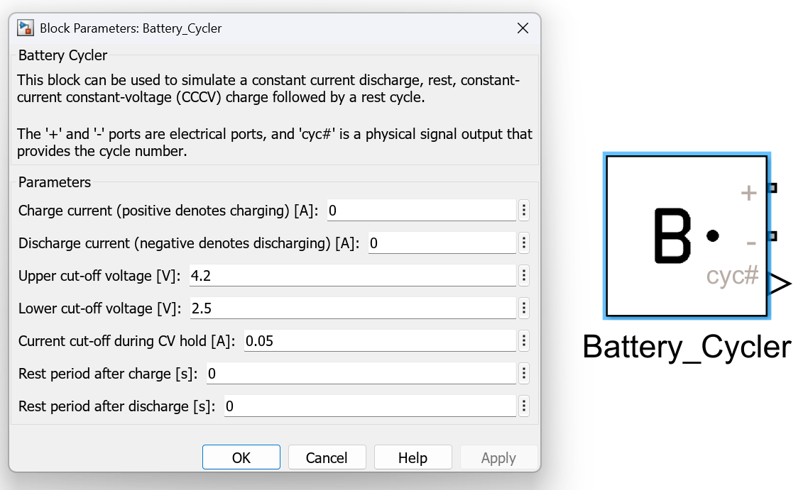
The Battery Cycler block has seven parameters which must be defined:
| Parameter | Description | Unit |
|---|---|---|
| Charge current (> 0 denotes charging) | The CC charge current applied during the charging phase | A |
| Discharge current (< 0 denotes discharging) | The CC discharge current applied during discharging phase | A |
| Upper cut-off voltage | CC charging current is applied until this value is reached, then CV charging continues at this voltage | V |
| Lower cut-off voltage | Discharge current is applied until this value is reached | V |
| Current cut-off during CV hold | CV charging will continue until charging current has reduced to this threshold | A |
| Rest period after charge | Duration of rest period following the charging phase | s |
| Rest period after discharge | Duration of rest period following the discharging phase | s |
Defining the number of cycles conducted
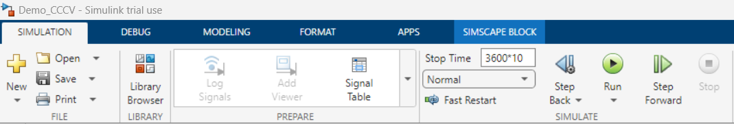
The number of cycles to perform is not explicitly defined, but rather implicitly controlled through the Simulink Stop Time defined.
This is located under the SIMULATION tab of Simulink, in the SIMULATE section.
For example, if one cycle will take approximately 1 hour (3600 seconds), then setting the stop time 3600*10 will provide approximately 10 cycles worth of data in the simulation.
Defining the cycling conditions graphically
The cycling conditions can be set in Simulink by:
- Double clicking on the
Battery Cycler, revealing theBlock Parameters. - Under the
Parametersfield, specifying the value of each of the seven parameters (see table above). - Click
OKto save the selection and close theBlock Parameters.
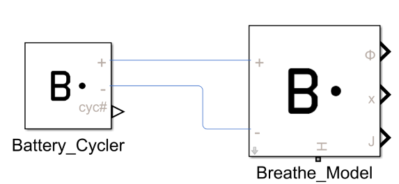
Outputting the electrical signal
The ports of the Battery Cycler block are the two electrical ports, labelled as + and -. These can be connected directly to Breathe Simulate to the matching ports.
As Battery Cycler and Breathe Simulate are both Simscape blocks, connecting these ports can be thought as analogous to connecting wires between these two entities.
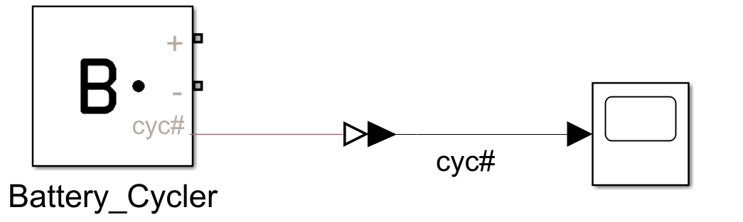
Outputting the number of cycles accrued
The Battery Cycler block includes a cyc# output. This is a physical signal (Simscape) that records the number of cycles that have been performed at any given time.
A cycle is defined as a Discharge > Rest > Charge > Rest (as specified at the start of this page).
This signal can be used to help with data processing and filtering.
As this port is a Physical Signal, it must be converted into a Simulink output type before it can interact with any Simulink blocks.
This can be done by simply using the PS-Simulink Converter utility, which is part of the Simscape library.
Worked example link
Refer to CCCV Cycling Demo to see the Battery Cycle block in action.