DCIR Cycler Block
The DCIR Cycler Block is a specialised battery testing component designed to perform Direct Current Internal Resistance (DCIR) measurements. This block can be used to simulate a standardised DCIR test protocol consisting of:
- Rest period (initial stabilisation)
- Current pulse (discharge)
- Rest period (recovery)
This sequence is considered a single DCIR measurement by the block.
This block emulates a typical DCIR experiment often performed in battery labs for characterising internal resistance. Simulating this behaviour with Breathe Simulate can, for example:
- Provide insight into the internal states the battery would have during DCIR testing,
- Screen for suitable pulse durations and rest periods to ensure accurate resistance measurements,
- Investigate model accuracy based on known DCIR data,
- Generate data required for ECM parameter estimation
Note: While this block can be used to simulate a constant current pulse, the primary use of this block is in ECM (Equivalent Circuit Model) generation workflows.

Specifying the DCIR test conditions
Defining the conditions of a DCIR test
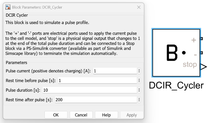
The DCIR Cycler Block has four parameters which must be defined:
| Parameter | Description | Unit |
|---|---|---|
| Pulse current | The discharge current applied during the pulse phase (negative values denote discharge) | A |
| Rest before pulse | Duration of rest period before applying the current pulse | s |
| Pulse duration | Duration of the current pulse | s |
| Rest after pulse | Duration of rest period following the pulse phase | s |
Defining the DCIR test conditions graphically
The DCIR test conditions can be set in Simulink by:
- Double clicking on the
DCIR Cycler Block, revealing theBlock Parameters. - Under the
Parametersfield, specifying the value of each of the four parameters (see table above). - Click
OKto save the selection and close theBlock Parameters.
Outputting the electrical signal
The ports of the DCIR Cycler Block are the two electrical ports, labelled as + and -. These can be connected directly to Breathe Simulate to the matching ports.
As DCIR Cycler Block and Breathe Simulate are both Simscape blocks, connecting these ports can be thought as analogous to connecting wires between these two entities.
Outputting the stop signal
The DCIR Cycler Block includes a stop output. This is a physical signal (Simscape) that indicates when the DCIR test sequence has completed.
The stop signal becomes active (value = 1) when the block enters the idle mode, which occurs after the rest period following the pulse has completed.
This signal can be used to help with data processing and to determine when the DCIR measurement is complete.
As this port is a Physical Signal, it must be converted into a Simulink output type before it can interact with any Simulink blocks.
This can be done by simply using the PS-Simulink Converter utility, which is part of the Simscape library.
ECM generation integration
This block is specifically designed to work with ECM generation workflows starting with a physics based model. The DCIR test data generated by this block provides the necessary current and voltage profiles required for:
- Parameter estimation of equivalent circuit model components
The standardised test protocol ensures consistent and reproducible results suitable for automated ECM generation processes.
Worked example links
Refer to ECM generation where the DCIR Cycler block gets used as part of the pulse synthesis process.