Creating a simulation
To build your first simulation, there are two components required:
- Breathe Simulate
- An electrical source to apply an appropriate electrical load
- (Optional) A thermal source for the thermal boundary or thermal load
Worked examples are included and documented to demonstrate different ways of combining these core components to drive insight. This page documents how to build up a simulation from scratch.
Create a new Simulink model
The first step is to create a Simulink model, a blank canvas, to start populating.
- In MATLAB, go to the toolbar and click
Home > New > Simulink Model. - If you don’t see “Simulink” in the Home tab, type
simulinkat the MATLAB command prompt and press Enter.
Add a Breathe Simulate block
A Breathe Simulate block is the heart of your new simulation, and based on the electrical and thermal sources, will model the behaviour of your battery. Refer to the Breathe Simulate block documentation for detailed description of the ports, block parameters, and outputs.
If you have followed the installation steps described in the documentation, you can double click on a blank space of the Simulink file and start to type Breathe Simulate which will bring the model block to include in the canvas.
Alternatively, you can navigate to the Breathe Simulate Library
- In the Simulink window, click
Library Browserin the toolbar. - If the Library Browser pane is hidden, press
Ctrl+Shift+Lor typeslLibraryBrowserat the MATLAB prompt. - In the Library Browser’s left-hand tree, expand
Breathe_Model_Library. - If you don’t see
Breathe_Model_LibrarypressF5or click theRefreshicon at the top of the Library Browser.
Drag and drop the Breathe Simulate block into your Simulink Model: In the Library Browser, under Breathe_Model_Library, click Breathe Simulate and drag it into your blank model canvas.
Set the Breathe Simulate block conditions
Double click on the Breathe Simulate block to open up the block parameters window. Here, you can define:
Parameter set:
Before running the simulation, you need to specify which parameter set the Breathe Simulate block should use. This is done by entering the desired parameter set ID in the block parameters.
For this example, we will use bmjn = 1000, which corresponds to the Moli P45B cell. You can find more details about parameter sets and how to work with them in the Parameter sets documentation.
To select the parameter set:
1. Double click the Breathe Simulate block to open its parameters window.
2. In the parameter set field, enter 1000 (or another valid ID as needed).
3. Click OK to confirm.
This ensures your simulation uses the correct cell parameters.
Initial conditions:
| Initial Condition | Description | Default | Unit |
|---|---|---|---|
| State of Charge (SoC) | Cell state of charge, where 0 ≤ SoC ≤ 1 | 0.5 | - |
| Cell temperature | Starting surface temperature of the cell | 25 | °C |
Degradation modes:
| Label | Description | Lower Bound | Upper Bound | Default | Unit |
|---|---|---|---|---|---|
LLI |
Loss of Lithium Inventory | 0.00 | 0.30 | 0 | - |
LAMNE |
Loss of Active Material in the Negative Electrode | 0.00 | 0.30 | 0 | - |
LAMPE |
Loss of Active Material in the Positive Electrode | 0.00 | 0.30 | 0 | - |
In this example we will set the initial state of charge to 1 and leave all other values at default.
Capture the Breathe Simulate outputs to be logged
The outputs of Breathe Simulate are grouped accordingly:
| Bus Type | Signal Name | Description | Units |
|---|---|---|---|
| Potential Bus (φ) | voltModel |
The terminal voltage of the cell | V |
voltAnode |
The anode potential of the cell | V | |
voltCathode |
The cathode potential of the cell | V | |
ocvModel |
The open-circuit-voltage of the cell | V | |
ocvAnode |
The anode open-circuit voltage | V | |
ocvCathode |
The cathode open-circuit voltage | V | |
tempSurfaceModel |
The cell surface temperature | °C | |
| States Bus (x) | socModel |
The state-of-charge of the full cell | - |
socAnode |
The state-of-charge of the anode electrode | - | |
socCathode |
The state-of-charge of the cathode electrode | - | |
| Flux Bus (J) | currModel |
The cell current | A |
heatFlowModel |
Heat generated from the cell | W |
These can be viewed using the built in Data Inspector tool by enabling Log Signals for the three output buses:
- Double click on a blank part of the Simulink Model to open Simulink's
Search blockfunctionality. - Type
Bus creatorand select theBus creatorSimulink block. - Connect all three output buses of
Breathe Simulateto the inputs of theBus creator. - Highlight each of the three buses connecting the outputs of
Breathe Simulateto the inputs of theBus creator. - With the buses highlighted, enable
Log Signalsvia the Simulink toolbar:SIMULATION > PREPARE > LOG SIGNALS.
Add an electrical source
A simple way to control your Breathe Simulate, is to use the Electrical Source block included in your Breathe Simulate library download.
Detailed Electrical Source block documentation is available for further information.
Double click on a blank space of the Simulink file and start to type Electrical Source which will bring the model block to include in the canvas.
Or you can navigate back to the Breathe Simulate Library via the Library Browser in the toolbar and drag and drop the Electrical Source block into your Simulink model.
Defining the type of electrical control
The electrical source block can provide electrical signals of the type: current (A), voltage (V), and power (W). Current is the default setting (Mode = 0).
The Mode of the electrical source can be changed by double clicking on the Electrical Source block to open the block parameter window. Here, specifying a value of 0, 1, or 2 for Mode will determine the signal type:
| Value | Source type | Units |
|---|---|---|
| 0 | Current (default) | A |
| 1 | Voltage | V |
| 2 | Power | W |
Setting the signal magnitude
To set the magnitude of the electrical signal provided by the Electrical Source block, a Constant Simulink block in combination with a Simulink-PS Converter can be used:
- Double click on a blank part of the Simulink Model to open Simulink's
Search blockfunctionality. - Type
Constantand select theConstantSimulink block. - Double click a blank area of the Simulink Model to open the
Search blockfunctionality once again. - Type
Simulink-PS Converterand click it to add it to the Simulink Model.
Now, you can specify the magnitude of the Constant block by double clicking it to open up the block parameters window and entering a value. For current and power modes, a positive value corresponds to charging and negative being discharge. Here we will simulate a constant current discharge of 4.5 A and set the value to -4.5.
Adding a solver and electrical reference (grounding).
Simscape models, unlike Simulink models, form a network. To enable any Simscape simulation we need to indicate the reference point and include a Solver configuration block within the network.
- Double click on a blank part of the Simulink Model to open Simulink's
Search blockfunctionality. - Type
Solver configurationand select theSolver configuration. - Double click on a blank part of the Simulink Model to open Simulink's
Search blockfunctionality. - Type
Electrical Referenceand select theElectrical ReferenceSimscape block.
Connecting the ports to Breathe Simulate
- Connect the positive port of the
Electrical Sourceblock to the positive port of theBreathe Simulateblock - Connect the negative port of the
Electrical Sourceblock to the negative port of theBreathe Simulateblock - Connect the output of the
Constantto the input of theSimulink-PS Converter. - Then, connect the input of the
Simulink-PS Converterto the input of the Electrical Source block. - Connect the output of the
Solver configurationblock to any part of the model, here we will connect it to the negative signal connecting the negative port of theElectrical source. - Connect the
Electrical Referenceto the negative signal of theElectrical Source.
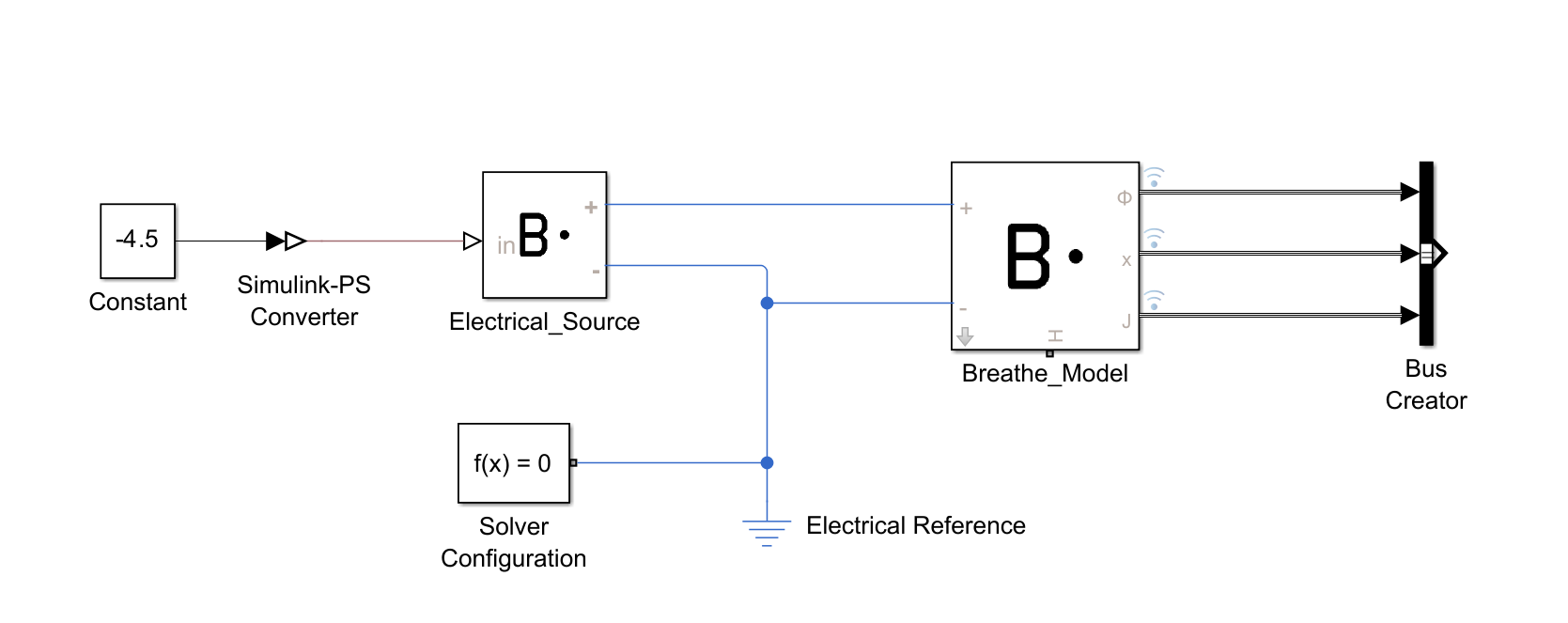
Your Simulink file should now resemble the block arrangement shown here:
Define the terminating condition
The Stop time is defined in the Simulink toolbar and can be defined by entering a value (units of seconds) into the dialogue box at SIMULATION > SIMULATE > STOP TIME. Here we will do a 1 hour simulation and set the stop time to 3600.
Running the simulation
The simulation can be run via the Simulate model button. In the Simulink toolbar, the button is located at SIMULATION > SIMULATE > RUN.
A progress bar will appear along the bottom of the Simulink window while the simulation is ongoing. Once complete, the status in the bottom left corner will indicate Ready.
Visualising the results
The outputs of Breathe Simulate recorded during the simulation can be viewed using the Simulink Data Inspector. This can be accessed via the Simulink toolbar: SIMULATION > REVIEW RESULTS > Data Inspector tool.
This is built in Simulink functionality, the detailed documentation for which can be found in MathWorks' Simulation Data Inspector documentation.
(Optional) Add a thermal source
Adding a thermal source enables you to define the thermal conditions of the simulated battery cell. Here we assume that the cell is exposed to ambient temperature via convective heat transfer.
This is done using two components:
Convective heat transfer- which dictates the heat transfer from Breathe Simulate to the ambient environmentTemperature source- which defines the ambient temperature
Both of these are part of the standard Simscape library and can be added by:
- Double click on a blank part of the Simulink Model to open Simulink's
Search blockfunctionality. - Type
Convective heat transferand select theConvective heat transferSimscape block. - Double click on a blank part of the Simulink Model to open Simulink's
Search blockfunctionality. - Type
Temperature sourceand select theTemperature sourceSimscape block.
Configuring the Convective heat transfer
This dictates the heat transfer from the Breathe Simulate to the ambient heat source, modelling heat transfer via fluid motion.
Three parameters are needed to define this behaviour:
| Parameter | Value | Unit |
|---|---|---|
| Convection Type | Constant | - |
| Cell surface area | Cell dependent | m2 |
| Heat transfer coefficient | 35 | W/(K·m2) |
Where a heat transfer coefficient value of 35 W/(K*m2) simulates heat transfer behaviour akin to air.
The Surface area of the cell model being used can be found in the meta information section of the corresponding parameter JSON file. For the MoliP45B cell example used here, the cell area value is 0.00537 m2.
This is a standard Simscape block. If further details are needed, refer to the MathWorks' Convective Heat Transfer documentation.
Configuring Temperature source
The Temperature source block enables the definition of a constant source of thermal energy. It is an ideal source which remains constant regardless of the heat added/removed from the Breathe Simulate block.
The only parameter for this block is the constant temperature, which can be used to define the ambient temperature, e.g. 25°C.
This is a standard Simscape block. If further details are needed, refer to the MathWorks' Temperature Source documentation.
Define further terminating conditions
By default, the simulation will execute until the Stop time value has been met (the duration for which the simulation covers). However, it may be of interest to define additional terminating conditions, related to voltage or state of charge, for example.
The Stop time is defined in the Simulink toolbar and can be defined by entering a value (units of seconds) into the dialogue box at SIMULATION > SIMULATE > STOP TIME.
Alternatively, simulation-dependent terminating conditions can be defined. For example, to utilise the Breathe Simulate output signals to define the terminating conditions, they first must be isolated from the output bus:
- Identify the bus in which the signal(s) you would like to use for terminating conditions in the Breathe Simulate block documentation.
- Double click on a blank part of the Simulink Model to open Simulink's
Search blockfunctionality. - Type
Bus selectorand select theBus selector. - Drag the output bus from the Breathe Simulate block to the input of the
Bus selector. Each bus needs its ownBus selectorif the signals required are distributed across multiple buses. - Double click the
Bus selectorto bring up the block parameters window. - For the top box
Elements in the bus, select each signal you would like to save and click theSelect elementsbutton in the top left to add it to theSelected elementsdialogue box below. - Remove any unwanted signals from the
Selected elementsdialogue box by selecting it and clicking the rubbish bin icon. - Click
OKto exit and save your selections.
Now, the signals are available for use in conditional arguments, such as the Compare to constant block which can be used to define a terminating condition when a value has exceeded a threshold.
For example, to set the terminating condition to when cell voltage (voltModel) exceeds 4.20V:
- Double click on a blank part of the Simulink Model to open Simulink's
Search blockfunctionality. - Type
Compare to constantand select theCompare to constantblock. - Connect the
voltModelsignal isolated using theBus selector, as described above, to the input of theCompare to constantblock. - Double click the
Compare to constantblock and define the operator and the constant value. In this case,Operator: >, andConstant value = 4.20. - Double click on a blank part of the Simulink Model to open Simulink's
Search blockfunctionality. - Type
Stop simulationand select theStop simulationblock. - Connect the output of the
Compare to constantblock to theStop simulationblock input.
An example of implementing such custom terminating conditions and thermal boundary conditions using Breathe Simulate output signals is provided in the Discharging. This demo shows how to configure the simulation to stop automatically based on cell voltage or other criteria, following the approach described above.